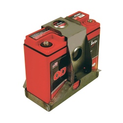
Cartek GT Solid State battery isolation kit, designed to be mounted to the chassis close to the battery, to allow you to keep the power cables as short as possible. Installation requires one external kill button and one internal on-off switch, these are interconnected using low voltage wiring.
The flexibility of this system does allow for additional kill switch buttons or devices to be incorporated, as well as full operation using just a single on/off switch as necessary. Microprocessor controlled incorporating false trigger detection, internal temperature monitoring and short-circuit protection offer unrivalled safety.
Thse units are extremely small and lightweight, weighing just 150g. Suitable for use with all types of vehicle including high compression and large capacity V8 engines.
Kit contents:
- Main GT battery isolation unit
- IP67 external kill button in red
- Internal on/off button in blue
- Cartek safety on/off stickers
Is the Cartek Isolator FIA Approved?
Unlike race seats, harnesses and fire extinguishers the FIA does not have an approval procedure for Master Switches. However, most FIA race and rally championships require cars to be fitted with a spark-proof master switch to isolate the battery from all electrical systems and stop the engine. The Cartek Battery Isolator meets these requirements.
FIA ARTICLE 13 : GENERAL CIRCUIT BREAKER
The general circuit breaker must cut all electrical circuits, battery, alternator or dynamo, lights, hooters, ignition, electrical controls, etc. and must also stop the engine.
MSA: EXTERNAL CIRCUIT BREAKER
8.1. The circuit breaker, when operated, must isolate all electrical circuits with the exception of those that operate fire extinguishers.
How Does It work?
The Solid State Isolator contains two isolation circuits. The first breaks the connection between the negative side of the vehicle’s battery from chassis/earth, thereby isolating the battery power from all electrical circuits, while the second cuts power to the engine electrics and thereby stops the engine from running.
Why Solid State?
Solid State means no moving parts, all power switching is fully electronic. Early types of electrical isolation were by large mechanical master-switches while more modern systems have utilised electro-mechanical solenoids. Both of these types of systems contain mechanical electrical contacts which, due to the combination of high electrical current and the shocks and vibration of the race car environment, sparking between the contacts occurs which results in contact erosion and eventual unreliability. This Solid State Isolator is also filled with a hard setting resin which prevents any ingress of dust, dirt or water therefore further increasing its strength and reliability.
How Is It Controlled?
The two electronic isolation circuits are controlled by microprocessors and incorporate various safety systems including over-temperature and over-current monitoring. These microprocessors also monitor the kill switches/buttons for instant activation without false triggering. The unit will instantly trigger into isolation mode when any of the kill buttons are struck or on detection of any fault or break in switch wiring circuits.
How Is It Operated?
The Isolator can be controlled by any number of switches although the usual configuration is one internal on-off switch and one external kill button. All switches/push-buttons are connected to the Isolator via light weight, low current wiring.
If required, multiple kill switches/devices can be incorporated, alternatively the system can be configured to be operated by a single on-off switch/push button. The Isolator will also automatically trip into isolation mode if any wire connection becomes broken due to fatigue or accident.
The Cartek Battery Isolator GT provides two functions. [1] To Disconnect the Battery from all Electrical Circuits and [2] to Stop the Engine.
Watch this animation to see how it works!

Battery Isolation
The Battery Isolators work by being fitted in between the negative side of the battery and the chassis ( As seen above ). When the external kill button has been activated or the internal button been switched to the off state, then the Battery Isolator will disconnect the negative side of the battery from the Chassis. This means that no power can get to any of the electrical circuits as there is a break in the circuit.
Engine Kill
The Cartek Battery Isolator GT kills the engine by taking in a fixed 12v input and sending a 12v output that would power your Ignition or ECU. When the negative side of the battery has been disconnected it will also cut the 12v output powering your Ignition or ECU. This will kill the engine.
Built in Protection
The Cartek Battery Isolator GT comes with built in alternator run down protection meaning no extra wiring and no extra components.
How Is It Controlled?
The two electronic isolation circuits are controlled by microprocessors and incorporate various safety systems including over-temperature and over-current monitoring. These microprocessors also monitor the kill switches/buttons for instant activation without false triggering.